|
||||||
Digital frequency counter by RU3AEP
General things
The frequency measurement is one of the most important things in radio construction. Without it you will be unable to set desired frequency in your receiver (and in transmitter too!), without it you will be unable to monitor frequency drifts etc. Sometimes, frequency counter can be used to verify, whether the oscillator works and ensure the stability of the generation.
Measurement of the frequency with ultimate precision, compared to other measurements is incredible simple. You may easily measure 1 MHz frequency with resolution 0.1 - 1 Hz and precision up to 1-5 Hz. Could you measure 1V with precision 5 microvolts? I think, no and never!
The idea of frequency measurement is quite simple - you just count the number of impulses during fixed time interval. If the time interval has length 1 second, the result will be directly in hertz. The precision is determined only by precision of time intervals, but the latter are usually formed from high-stable quartz oscillator. Typical counter consists on the following parts: reference oscillator, counter with indication, input trigger and control circuits. Reference oscillator together with control circuits forms fixed time interval as well as reset impulses for counters. The input signal passes through input amplifier and trigger, becoming the levels used by ICs. Then the impulse sequence formed goes to the 'gate', which periodically opens for precise time determined by control circuit. During this time, counters accumulate the result, which is displayed. The structure diagram of my unit is shown below:
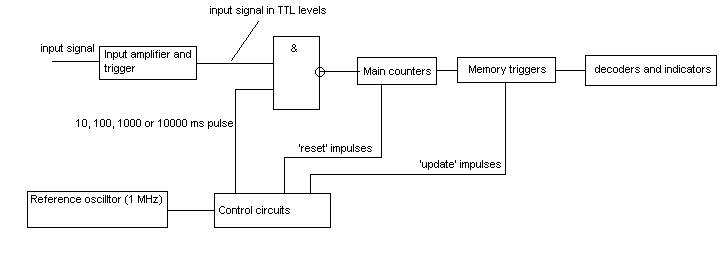
In my unit to add to all standard parts internal memory triggers are introduced to make measurements more convenient and fast. If output indicators are connected directly (trough corresponding decoders) to the counters, the digits are 'blinking' during measurement, and it is required to make additional time of indication, during which counters are idle. This reduces the ease of readout and speed of measurement. If there is internal memory, you can make counters working almost all the time and update the information on indicators only after the cycle of counting is done. During the cycle the previous result is shown. To implement this principle, the control circuit forms impulses for the gate opening (length 10, 100, 1000 or 10000 ms depending on the position of the switch), for counters reset and for the opening of memory triggers for writing. After the counting time is finished, the information in triggers is updated by short pulse, and then counters are reset. The time diagram is following:
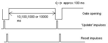
The time between measurements (~100 ms) is chosen from the following considerations: if it is too short, on short measurement times the frequency of display updating becomes too high (up to 100 Hz), which is too inconvenient for eyes. By the the value chosen here the maximum frequency of display updating is limited by 10 Hz, which is good enough from viewpoints of service and measurement speed.
Construction
The unit is made on K155 (SN74) TTL chips. They are rather cheap and work up to 30 MHz, which is sufficient for tuning all hamradio and broadcasting SW equipment. To extend the frequency range, optional pre-divider may be connected to the input, which divides the input frequency by 10. The latter is made on K500 ECL - chips (ECL - abbreviated Emitter Coupled Logic), which work up to 200 MHz. All the construction can be divided by four parts, which are actually made on separate boards:
main counter with memory triggers and indicators
control device with input circuits and reference oscillator
high-speed pre-divider
power supply (this is quite simple, consisting only on the transformer, four diodes, two filtering caps (for +5 and -5V) and two integral voltage stabilisers. The only thing should be noticed that transformer must be powerful enough to feed so many chips and so many LED indicators, because total current consumed from +5V is about 1.5 A!).
Main counter board
Main counter has 6 identical decades. Each decade consists on counter (K155IE2), memory triggers (four triggers in one K155TM7 chip), decoders for transformation four-bit code into code required by 7-segment indicators (K514ID2) and LED indicator (ALS335B). All reset inputs of counters are combined together, the same is done with C-inputs of triggers. To avoid difficulties in driving so many inputs simultaneously by an external signal, a powerful repeaters made from two inverters (K155LA12 chips) are introduced onto 'reset' and 'update' inputs of the block. To add to this, main counter board has a circuit for controlling the 'overload' LED, which is turned on in case of counter overloading. The principal circuit (excluding pin numbers, sorry!!) is here:
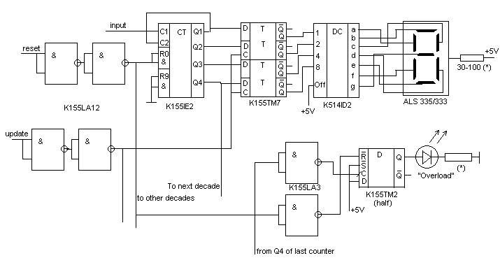
The schematics here is quite straightforward: there are 6 identical decades (only one is shown on the picture), which are connected in series. From the last output (Q4) of the last counter the signal goes to the overload control circuit. The latter consists on two inverters, D-trigger and LED indicator.
If the total number of impulses counted during counting time exceed 999999, the level on the Q4 of last counter changes from 1 to 0. After the inverter, on the C input of trigger, it becomes be changing from 0 to 1 (rising). This makes the dynamical trigger to set the signal on its output according to potential on D input, which is constantly 5 V (logical 1). After the trigger is set, LED becomes to emit the light showing the overloading. The next reset impulse, after passing through inverter resets the trigger into previous state by means of R (inverted) input. Practically all the above means, that in case of overloading the LED is blinking in tact with measurement cycle.
Control device with input circuits and reference oscillator
This is the main one and the most complicated block in the whole construction. It performs the task of formation of 'update' and 'reset' impulses for the main counter board, as well as gate opening impulses. Also here the input signal of any wave form is converted into the TTL levels pulses for further digital treatment.
The 'heart' of digital frequency counter, which determines its precision is reference quartz oscillator. In the unit described here it is made on two inverters (155LA3) with the positive feedback on 1 MHz quartz crystal. If the actual frequency is not exactly 1 MHz, which is quite common situation due to crystal's parameters deviation and affecting of external capacities, additional small inductor or capacitor in series with resonator may be introduced to correct the situation.
1 MHz signal then passes through the chain of 1:10 dividers (3 K155IE2) becoming the frequency 1 KHz. This signal is routed to two chains of counters. The first one, consisting on 4 decades, is designed for the formation of gate opening impulses. After the specified number (10, 100, 1000 or 10000, depending on the position on the switch) is accumulated in these counters, the D-trigger is set in 'zero' state through its C-input. This causes high potential on the trigger's inverted output, which is connected with the reset inputs of all four counters and they stop to work for a while. The direct output of the trigger (Q) drives the gate (third from left &-element on the bottom of the scheme). After the trigger is set in 'zero', gate closes, and simultaneously another chain consisting from two counters start to count 1 KHz impulses. The last counter in this chain is followed by "4 to10" decoder (K155ID6). After 10 impulses, signal on the '1' output of the latter becomes zero for a short time. After passing through inverter it is used for updating information on the display. By the same way the output '2' of the decoder is used to form the 'reset' impulses for main counter board. After about 100 ms from the moment of gate closing the signal on the '9' output of the decoder becomes zero, causing setting the D-trigger in the 'on' state. At this point the second chain of counters stops working, the gate opens again, and the cycle repeats.
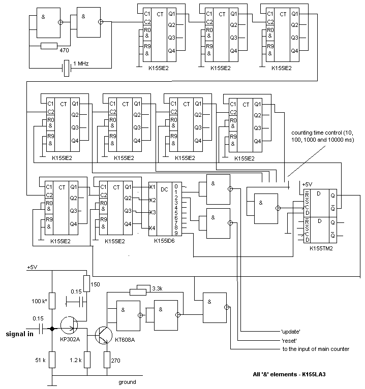
The input amplifier and trigger is made on two transistors - one junction FET and one bipolar and the trigger on two inverters. The resistor marked by a star, as well as a semi-variable resistor are chosen to provide the best sensitivity and stability of working. Though this circuits looks quite primitive, it has very flat frequency response, which is incredible difficult to achieve in complicated amplifiers, and reasonable sensitivity - about 150 mV in range from 100 Hz to 30-32 MHz. I tried many other circuits, but the results were much worse.
High-speed pre-divider
This module is made on ECL chips, which have upper working frequency up to 200 MHz and even more. The big disadvantage of ECLs is very high power consumption, but they are the only cheap devices which are able to work on several hundreds megahetz.
In order to reduce reflected waves in transmission lines between chips and ensure stable working of the latter on high frequencies, every output must be connected to power line (-5 V) through low-impedance resistors. That is why, there are so many 510 Ohm resistors in the schematics below.
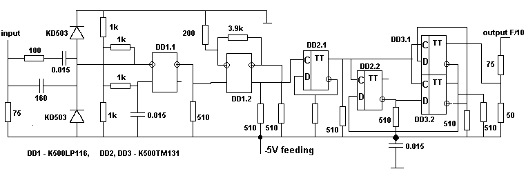
From the input, HF signal goes to inverted input of the first differentional amplifier, which is made on section DD1.1. To bias the amplifier, both inputs are fed by the half of power-supply's voltage, provided by the voltage divider. Two diodes serve to protect first stage from the signals, which are out of range for used IC's. This protection is quite reliable, one time i put the input of this device directly to my transceiver (!) in transmit mode, and nothig was burned!!! After the amplifier, signal goes to the Schmitt-type trigger, which is made on the same amplifier with resistive feedback (DD1.2). Here, it becomes the rectangular shape and ECL logic levels. From the trigger, impulses pass trough one T-trigger, which divides the frequency by two, and then - additional combination of three triggers with appropriate feedbacks divides the frequency by 5. The resulting signal becomes frequency F/10, where F - the frequency of input signal.
The amplitude of output signal is about 0.9 V and is sufficient for the main main board to be treated further. The upper frequency for such device becomes about 200 MHz, and the pre-divider demonstartes excellent sensetivity (50 mV and less), flat frequency response in range 0-100 MHz and stable working. To be able to provide maximal resolution, as well as to operate with high input impedance at low (<30 MHz) frequencies, high-speed pre-divider is turned on by the special switch. In 'off' position, it is bypassed.
I hope, that the information provided here was readable and comprehensive enough to understand my design and ideas, pick up some information and make the valuable instrument for your workshop.
If you have some information for me or/and you noticed some undiscussable errors, or you have some ideas - fell free, just write me a letter
73!, Valentin Gvozdev , RU3AEP.
| north carolina tax id |