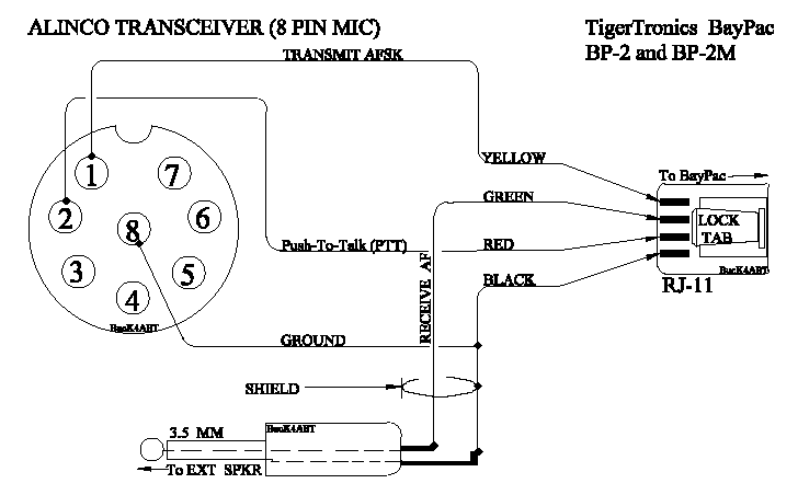
ALINCO 8 PIN MIC PORT TO THE "BAYPAC"

Alinco 8 Pin Mic I/O to BayPac BP-2 and BP-2M

Alinco 8 Pin Mic I/O to BayPac BP-2 and BP-2M
The following text provides additional information for PC comport and radio interfacing.

If your computer comport has a 9 pin (DE9) comport, use a "shielded" adapter cable
wired as follows:
DE9 Pin (COMport) 25 Pin (BayPac)3 - - - - - - - - - - 2 7 - - - - - - - - - - 4 8 - - - - - - - - - - 5 6 - - - - - - - - - - 6 5 - - - - - - - - - - 7 4 - - - - - - - - - - 20
The Radio port interface to the BayPac utilizes an RJ-11 4 PIN Telephone type connector:1) Connect the microphone input to the YELLOW wire of the BayPac RJ-11 connector. 2) Connect the radio ground/shield lead to BLACK wire of the BayPac RJ-11 connector. 3) Connect the radio PTT input of the radio to RED wire of the BayPac RJ-11 connector. 4) Connect the radio external speaker to GREEN wire of the BayPac (see text below). Connect External Speaker to the speaker output of the radio.