
The Packet Radio Operator’s Journal

APRIL 1999
Volume 6.04Prices for the ''Purchase Options'' shown at the bottom of this page DO NOT include shipping costs. All shipments must be via UPS. No orders shipped outside the USA.
For some who read this SEDANewsLetter, but who are not familiar with the Southeastern Emergency Digital Association Networks SEDAN, it is a network of more than 200 nodes that cover 11 States. The primary purpose of this network is for disaster and emergency communications when and if a disaster or impending danger threatens an area within earshot of one of the SEDAN local access nodes.
The SEDAN operates as a keyboard to keyboard Packet Radio network when not in emergency communications use. By allowing it to be used for keyboard to keyboard use, we are always assured of the continuity of the SEDAN. If a discontinuity appears in the network, a user will alert the local System Node Operator (SNO) of a failed node, so that repairs can be quickly made to return the system to full service.
The network has more than fifty, 60 watt, 9600 baud backbone nodes operating on 6 meters. The local access (1200 baud) nodes are operating at primarily 145.770 MHz with a few local access nodes and secondary gateways to the 9600 baud backbone on other two meter and 440 MHz frequencies.
IT'S A "DELTA DAWN:"
In an effort to replace some of the SEDAN low power (10 to 25 watt node), radios with some 50 + watt transceivers, I recently began a search for some GE Phoenix SX transceivers. I had learned of a bid sale from a local railroad system and some others from the forestry service. I was able to get ten Phoenix SX on one bid, but lost on the other.
Then a friend told me about another radio that would better serve our purpose. It is an GE (ERICSSON) 110 watt, transceiver called the "DELTA," and it is of recent vintage.
The GE DELTA "S" (narrow-band) with an "SX" (wide-band) PROM will function well in a high RF environment. Mostly because the "S" model utilizes cavity resonators in the front-end (receive RF section), and with the "SX" Micro (PROM), it will easily move into the 136 to 150 MHz region.
In addition, the Delta's I found, run 110 plus watts! These are radios that were just removed from commercial service and are in very good condition.
The DELTA "S" and "SX" was built in three band cuts... e.g.; Low band (29 to 50 MHz), High band.. low split 136-155 MHz, high split 152-174 MHz, and UHF. Best remembered because it came in two power levels for VHF and mainly because it was built to withstand heavy abuse. The two VHF versions were 50 watt and 110 watts "output".
The DELTA was somewhat ahead of its time because it applied the same surface mount device technology that are used in today's communications assemblies.
These 110 watt, DELTA "S" ''Narrowband'' are the version with the "SX" micro installed.
NOTE: FYI, I have listed the MICRO part numbers for most GE DELTA and ERICSSON Ranger below:
19A703241G1-G8 DELTA/S UHF/VHF MICRO
19A703868G1-G5 & G7 DELTA/SX UHF/VHF MICRO
19A703244G20-G23 DELTA/SX UHF/VHF and RANGR VHF MICRO
19A703868G6 Special for RANGR UHF only
19C851149G1-G4 DELTA/S Low Band MICRO
19C851149G5-G12 DELTA/SX Low Band MICRO
19C851591G1 DELTA/S Low Band MICRO (SOLDER IN FIELD KIT)
19C851591G2-G3 DELTA/SX Low Band MICRO (SOLDER IN FIELD KIT)
By using the narrow band "S" DELTA with the "SX" PROM, I can set it for single frequency node use and tune the helical resonators in the RF section for a "hot" front end at 145.770 MHz that works great in an RF rich environment.
In a similar fashion, but with a few more parts and tuning procedures, I can make it into a full blown, 110 watt, 16 channel Packet Radio. More on the sixteen channel mod later..
FIRST THINGS, FIRST:
I first test the radio to insure that I have a good "working" radio, then I begin my modifications to the Delta. If you perform the modifications shown in this article, you will NOT need the cables, and control head accessories for the DELTA.
You can test the DELTA by building an interface cable similar to that shown at figure one. This connector (P1) uses (GE/ERICSSON Part number(s) (cover=19C850508P1), (connector=19D900037P1), and (housing=19D900015P1), I cannot supply these parts.
I do not use the "P1" connector; Instead I build the interface I've drawn as figure two. I do a bit of surgery to the front of the DELTA (see figure 3), and insert the TNC cable at the DELTA front. Then I make a couple of 3/16th inch holes for the DC power input wires at the rear (see figure 4).
THERE IS POW! POWER IN THE DELTA:
If you know the "personality" (frequency, usually 16 channels) of the radio you are working with, you can build the simple test interface that I have drawn at figure one. Although I am showing the DELTA "P1" plug interfaced to the MFJ-1270 connector, this same plug and five pin DIN combo can easily be used to test the operability of the GE DELTA radios.
Always perform a preliminary test of the radio, and do so into a purely resistive dummy load... rated at more than the power output of the radio... e.g. 110 watts... PLUS. Just so you know... I've seen much more than 150 watts out of some of these radios!... so do beware, and remember R23.. more on the application of R23 later. While making modifications to several of the GE/ERICSSON DELTA radios, I've been able to crank as high as 175 watts of power output from them. Yes, I know... the temptation is to run the power up, but the high powered VHF DELTA radio is spec'd at 110 watts output. BUT REMEMBER, you will need a 25 to 30 ampere, 13 Volt DC supply for this high powered beast!
OK, so we are using the DELTA in the Packet radio service, so maybe I will crank it up a tad more... but not much over... a hundred and .."rty" watts. AND only because I know that in Packet Radio service, "the 110 watt DELTA will only be keyed for a few seconds at time." Let's keep in mind that if 110 watts don't get you there, then the target node or Packet station is; 1) deaf, or 2) too far away.
Here is how to maintain power control of the DELTA 110 watt radio. If the radio is running over ... let's say; 140 watts, the power can be reduced by turning R23 counter-clockwise. R23 is located in the RF PA compartment at the left side of the DELTA (component side up) radio. If the metal cover is in place on the RF PA, there will be a single hole near the right front of the RF PA cover.
Once you have the interface complete as shown in figure two, use pin 3 of the 5 pin DIN to ground to test (PTT) the transmit of the DELTA. Use a small amplifier (or earphone) attached to pin 4 of the 5 pin DIN to check the receive. As shown, the pin connection I've used to attach for TNC receive audio is "unsquelched" allowing you to hear white noise on the test speaker. The audio receive ground will be to pin 2 of the 5 pin DIN connector. This is one reason I recommend the MFJ-1270B, or C, TNC for X1J4 node service, as it will operate with radios that have "open" or unsquelched receive audio.
With the higher power and even though they are syntheized, the DELTA does exhibit a fast rise-time to full power, and they do have a very fast antenna change-over relay, so the TXDelay of the node will not change from the TXDelay of 35 that we now use with the 1200 baud node radios.
DEALING WITH FIGURE TWO:
An alternate method to interface the DELTA to an MFJ-1270B or C TNC is shown in figure two. This is how I interface all my DELTA to X1J4 nodes. One caveat... If you make the mod as I have, using the interface at figure 2, then be sure to cover, or use heat shrink tubing to cover pins 37, 16, and 19 on the front (J601) radio connector. The location of these pins are shown and labeled in figure one (1).
After you're confident that you have a good working DELTA, the next step is to remove power, and remove any tone (Channel Guard) board from the radio (if it has one). Toss it away.... far away, you will no longer have a use for this PCB. To remove the CG PC board, open the top of the DELTA. The "CG" PCB is located near the front of the DELTA in the left front section with the solder traces exposed or facing up. Remove the four (4) TORX retaining screws. Now lift.. that is, it may need a slight tug, to remove the CG PCB. Remove the small "extender" PCB also.
Next; Locate jumper pins J608 and J609. These pins will be directly below where the CG PC board was located. If the radio was equipped with channel guard, then a jumper (strapping option) will be present on J609. Move (remove) the jumper (P609) from pins J609 and move it left to J608. place the jumper on J608 where it becomes "P608."
ADDRESSING THE EEPROM:
At socket U706 is the IC 2212 EEPROM. This is where the "personality" of the DELTA is stored. If you have a friend who has the GE "suitcase" programmer, you can obtain the 2212 EEPROM and have the friend burn the 16 Packet channels of your choice into it.... or you send me the EEPROM from U706 and I will program it FREE if it is to be used on a SEDAN node site. If it is NOT to be used as a SEDAN node radio, then include $15.00 for the programming. If you do not have a EEPROM in socket U706, then include $25.00 with your order and I will supply the "programmed" EEPROM. Be sure to include a list of the 16 VHF Packet frequencies you want in the EEPROM, and your address!
When making the program selection in the "suitcase programmer," I use the "high-split" (152-174) version selection. We can force the radio (EEPROM) to accept frequencies down to 144.5 MHz. To do this, use the "insert" key on the programmer instead of the <Enter> key.
WE'VE GOT "PERSONALITY:"
In the following table, I have provided a set of the frequencies that I put into most of my EEPROMs. This set of frequencies include the SEDAN frequency of 145.770 as channel 1, and both the old and the new APRS frequencies at channel 15 and 16.
I MAKE NO PROMISES THAT THESE RADIOS WILL PERFORM BELOW 145 MHz.1. 145.770 SEDAN
2. 145.010
3. 145.030
4. 145.050
5. 145.070
6. 145.090 (some DX Spotters)
7. 145.570
8. 145.610
9. 145.630
10. 145.650
11. 145.670
12. 145.690
13. 145.730 (some DX Spotters)
14. 145.750
15. 144.390 APRS (new)
16. 145.790 APRS (old)
TABLE 1
You can configure your radio personality in whatever sequence you wish.
SYSTEM ALIGNMENT:
Now that we have the EEPROM programmed and installed at U706, it is time to do the final touchup to the DELTA. You may wish to make a copy of this SEDANewsLetter so you can switch between pages and text to view the next alignment procedure or test point.
I am a strong believer in, " A picture is worth 10,000 words. So to make your life easier, I have drawn an extensive overview of the DELTA radio tuning points and voltage monitoring points within the radio (see figure 5). Stop for a moment and study the drawing at figure five and the steps I have outlined. By reviewing this drawing now, may save some time later when you get into the nitty-gritty of the modification.
First and foremost, read the text box shown in the upper right corner of figure 5. This section is first because you must be sure you have frequency lock of both the DELTA receive and transmit VCO's.
It is important that you use a DVM with the readout set for the 1 to 10 volt "DC" scale.... or that the DVM will auto-range to the scale you require.
SIXTEEN CANDLES:
As you become more familiar with your DELTA radio, you will soon learn how easy it is to make the DELTA into a 16 channel, 110 watt Packet Radio. We've discussed the use of the DELTA as a single channel mountain top node radio, but now let's talk about utilizing the fuller potential of the Delta's sixteen channel capability.
At figure 6, I've outlined a simple BCD switching arrangement that will enable you to "switch" to any one of the sixteen channels programmed into your 2212 EEPROM (U706). In TABLE 2, I'm including the "truth table" that supports this switching arrangement.
FB1 - FB2 - FB3 - FB4
ON OFF OFF OFF
OFF ON OFF OFF
ON ON OFF OFF
OFF OFF ON OFF
ON OFF ON OFF
OFF ON ON OFF
ON ON ON OFF
OFF OFF OFF ON
ON OFF OFF ON
OFF ON OFF ON
ON ON OFF ON
OFF OFF ON ON
ON OFF ON ON
OFF ON ON ON
ON ON ON ON
OFF OFF OFF OFF
FB1, FB2, FB3, and FB4 are the pin identifiers for pins 1, 2, 3, and 4 at J601. Now that we are beginning to see the relationship between the channel numbers and the truth table, let's look at the switch configuration for the truth table and the list of frequencies that I use for Packet operation in the DELTA, shown as TABLE 3.
* CAVEAT...Frequency FB1 FB2 FB3 FB4 1. 145.770 ON OFF OFF OFF 2. 145.010 OFF ON OFF OFF 3. 145.030 ON ON OFF OFF 4. 145.050 OFF OFF ON OFF 5. 145.070 ON OFF ON OFF 6. 145.090 OFF ON ON OFF 7. 145.570 ON ON ON OFF 8. 145.610 OFF OFF OFF ON 9. 145.630 ON OFF OFF ON 10. 145.650 OFF ON OFF ON 11. 145.670 ON ON OFF ON 12. 145.690 OFF OFF ON ON 13. 145.730 ON OFF ON ON 14. 145.750 OFF ON ON ON 15.* 144.390 ON ON ON ON 16. 145.790 OFF OFF OFF OFF TABLE 3
I MAKE NO PROMISES THAT THE DELTA WILL OPERATE BELOW 145 MHz.
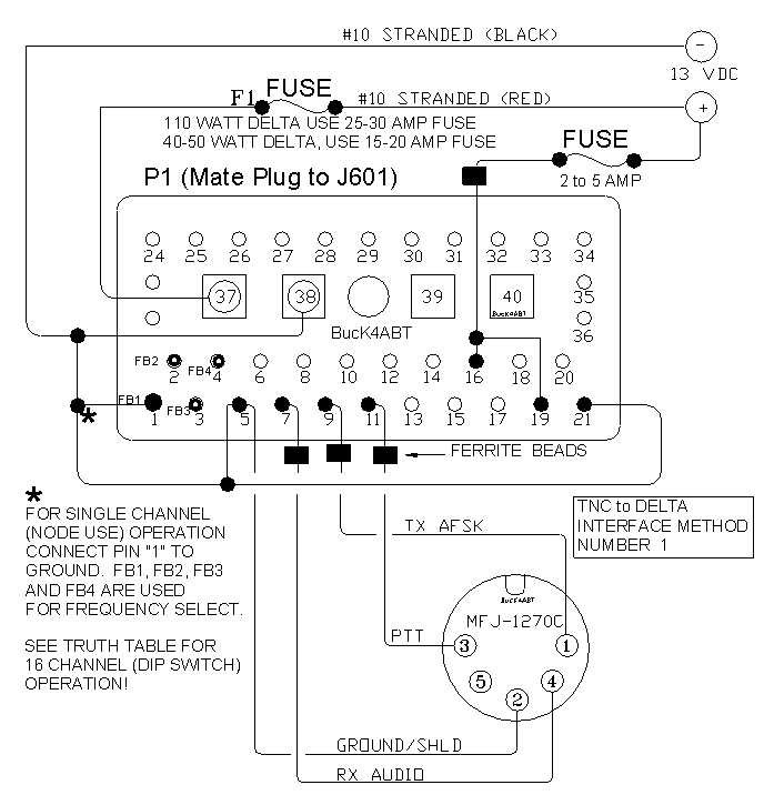
FIGURE 1
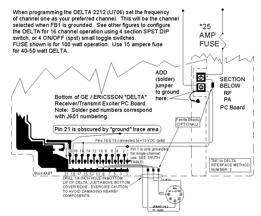
FIGURE 2
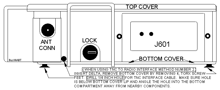
FIGURE 3

FIGURE 4
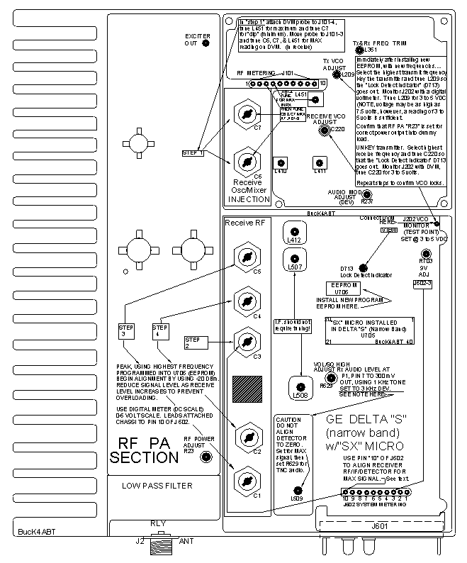
FIGURE 5
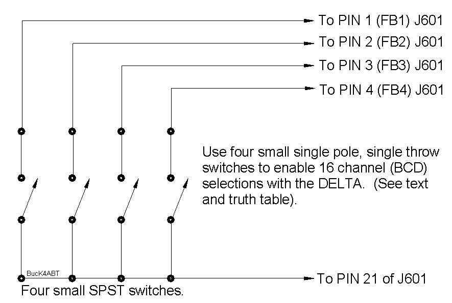
FIGURE 6
THE SUPPLY IS LIMITED ...:
(OPTION 1); If you don't have a source for the 110 watt, Narrow Band DELTA "S" with the "SX" Micro; I can supply a working (tested) Narrow Band Delta "S" with SX micro, ready for you to make the conversion and mods, for $125.00 dollars. The accessories are not needed to make the Packet Radio modifications I've described here. I do NOT have, and I cannot I supply the accessories..ie; control head, cables, etc…
.
Add $10.00 to radio price for UPS shipping and handling.
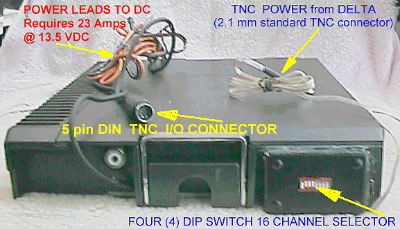
(OPTION TWO (2) ''PHOTO ABOVE''); 110 Watt, Delta SX with 20 Db Receive Preamp installed, ready to plug-n-play; I can supply a sixteen (16) channel, modified and tested, 110 Watt, Delta SX, with 16 (two meter VHF Packet frequencies programmed into the EEPROM), using a 4 position "DIP" switch for channel selection (DIP switch position for frequency selection, table included). This includes the switch setup (see figure 6) that enables switching between any of the 16 channels programmed into the 2212. This option is ready to "plug and play, and is $150.00 dollars (THE SUPPLY IS LIMITED).
Add $15.00 for UPS shipping and handling.
OPTION THREE (3) is for SEDAN SNO's ONLY! If you are a SEDAN System Node Operator and you want to add a new SEDANode or replace a low powered node radio with a real power house, then option 3 is for you. OPTION 3: I can supply a 110 Watt, Delta complete with all mods, aligned and tested, and set to 110 watts output on 145.770 MHz ONLY!, for $100.00 (supply is LIMITED)..
Add $15.00 to radio price for UPS shipping and handling.
OPTION FOUR SOLD OUT!; The PHOENIX SX (NON SCAN) are SOLD OUT!. SOLD OUT!.
THIS PHOENIX SX OFFER MAY BE WITHDRAWN SOON; SUPPLY IS SOLD OUT!
DEPLETED!
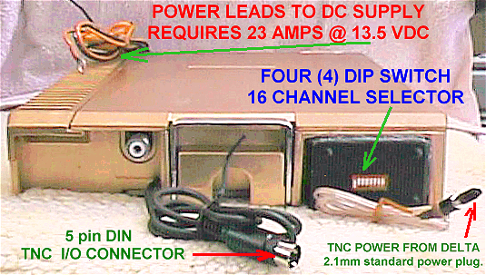
(OPTION FIVE; Photo Above) 9600 Baud, modified and tested 110 Watt, Delta SX with 20 Db Receive Preamp installed, and 16, two meter (VHF) Packet frequencies programmed into the EEPROM (4 position DIP switches are used for channel selection; Photo above). This includes the DIP switch setup (see figure 6) that enables switching between any of the 16 channels programmed into the 2212. This option is ready to "plug and play at 9600 bauds (and 1200 bauds), and is $200.00 dollars (LIMITED SUPPLY).
Add $15.00 to radio price for UPS shipping and handling.
OPTION SIXSOLD OUT!; The PHOENIX SX, sixteen channel (NON SCAN) Modified and tested at 9600 bauds are SOLD OUT!
THIS PHOENIX SX OFFER IS WITHDRAWN ; SUPPLY IS SOLD OUT!
DEPLETED!
If you need an EPROM to add a new SEDANode, BE SURE to include the callsign, SSID, and the alias of the new SEDAN node. The 27C512 (X1J4) EPROM is FREE for all SEDAN nodes.
NON SEDAN System Node Operator's, I burn EPROMs for the X1J4 Node code for the MFJ-1270"B" and "C", and other TNC2 compatible TNCees.
For EPROM order form, CLICK
HERE.
The radios listed above are shipped UPS and Packaging is air bubble wrapping. For Phoenix SX shipping; Add $10.00 to radio price, and for DELTA SX Shipping; Add $15.00 to radio price, UPS shipping and handling.
NO UNITS sold or shipped outside continental USA!
Radios that I modify, carry a 10 day replacement warranty. No other warranty is expressed or implied!
I DO NOT WARRANTY ANY RADIO MODIFIED BY OTHERS!
Make Check or Money Order payable to:
Buck Rogers
Mail To:
Buck Rogers K4ABT
115 Luenburg Drive
Evington, VA 24550-1705